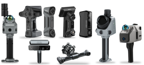
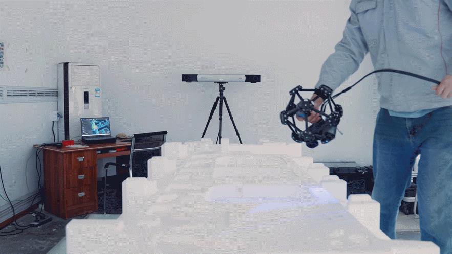
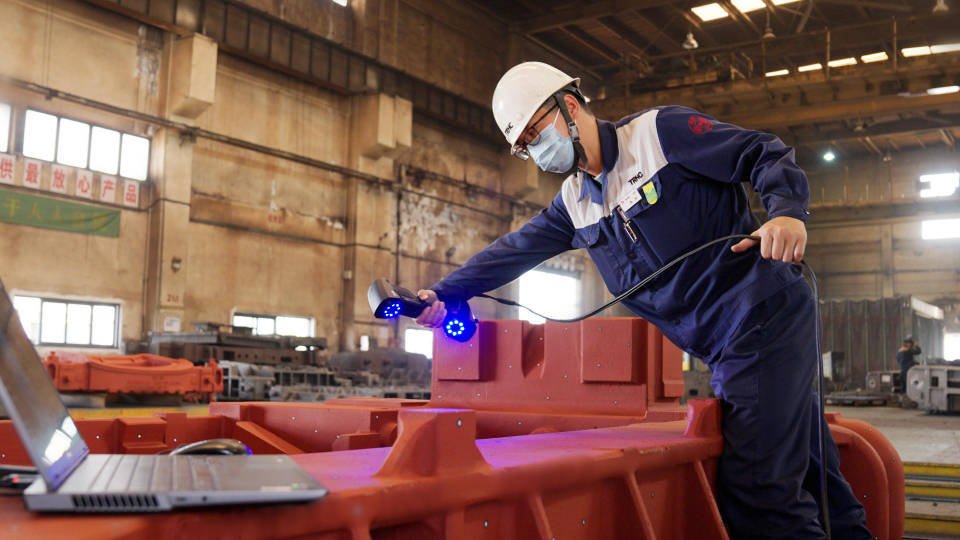
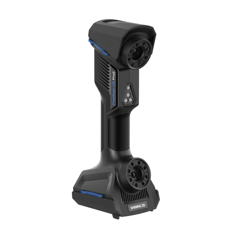
A mould or die changes with every cycle, and drawings rarely keep up. 3D scanning lets a tool room see the real geometry: how far a cavity has worn, how a repaired insert compares with the original, and what a modified tool looks like against the design. MAKE3D is the Official Distributor of Shining 3D in Malaysia, so we can supply metrology scanners for tool inspection and reverse engineering, industrial 3D printers for jigs and fixtures, or run the scanning and modelling as a service. Tell us the tool, its size and what you need to decide on WhatsApp and we will suggest the route.

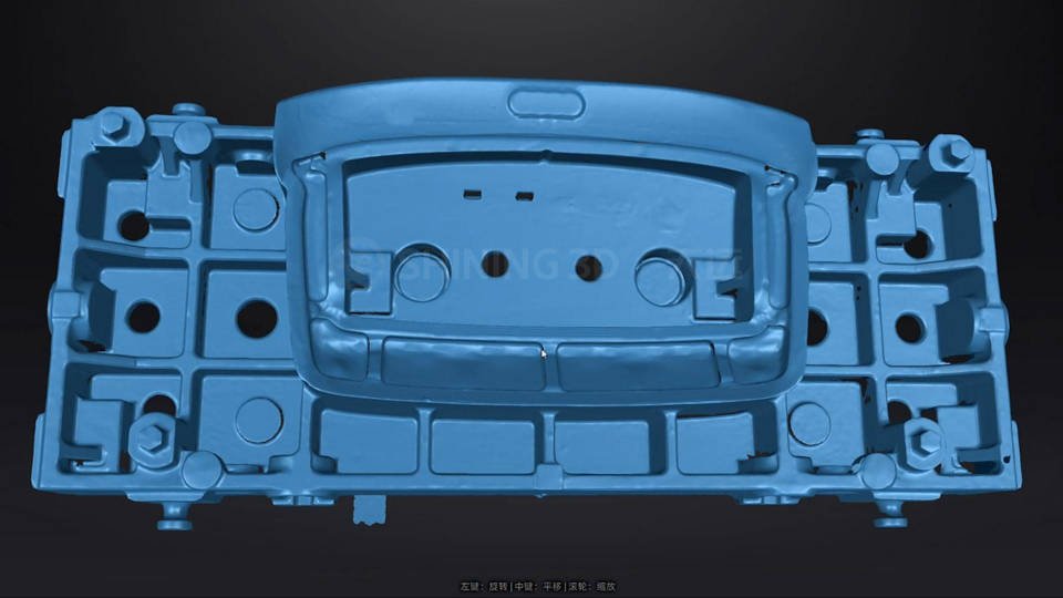
Scan the tool, then compare the scan with the original CAD or with an earlier scan of the same tool. The software shows a colour deviation map across the cavity, core, parting line and edges, plus section cuts at the places that matter. You see where material has worn away, where flash is starting and whether a repair held its shape.
Doing this at regular intervals turns tool condition into data: you can plan a refurbishment before parts drift out of tolerance, and compare tools that were meant to be identical. Scanning is non-contact, so polished surfaces are not touched by a probe. Shiny surfaces may need a light developer or spray to scan cleanly; we test your tool at the demo. Our 3D inspection service can do the first scan for you, so you see the workflow on your own tool.


Yes. When a tool has no drawing, or has been changed over the years, scanning captures its current state. From the scan you can design a repair insert, machine allowance for a modification or a replacement part to fit exactly, and check the result against the scan afterwards.
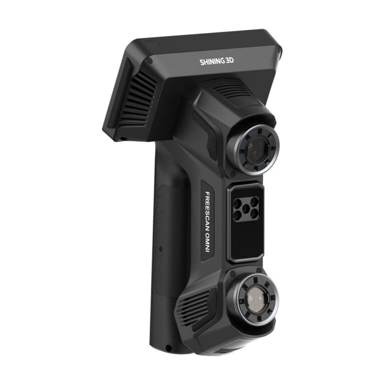
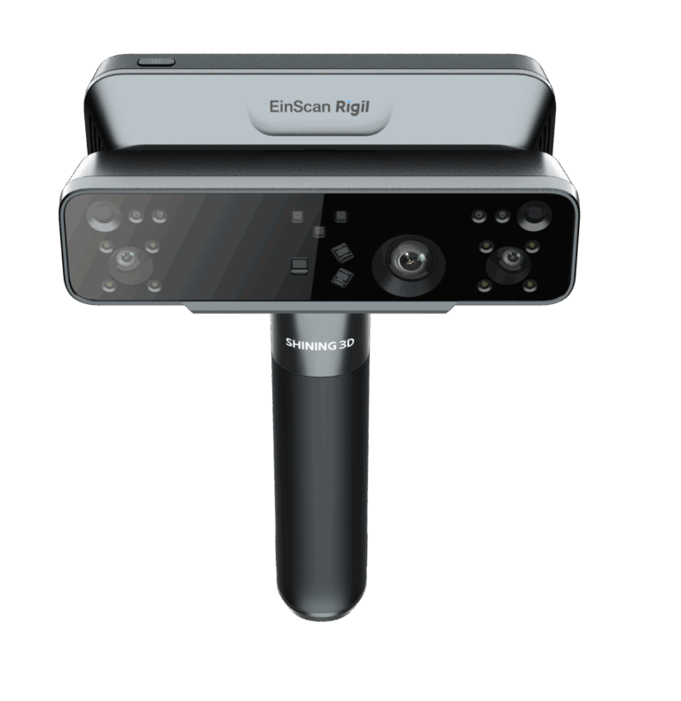
For a master pattern or hand-finished model, a scan captures the shape so that it can be copied or adjusted in CAD. We recommend the EinScan Rigil when the aim is a CAD model of a tool component, and a FreeScan model when the result must also be inspected against tight tolerances. Our reverse engineering service builds the CAD model from the scan. The scan is the geometry only; steel grade, heat treatment and finishing stay with your tool room.

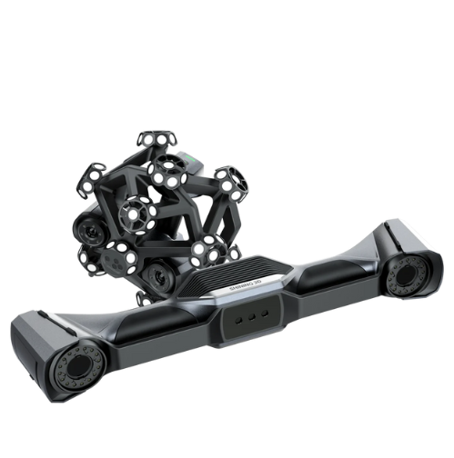
Pick the scanner by tool size and by whether you inspect, reverse engineer or both. The table lists the models we supply, with manufacturer figures from our product pages and the Shining 3D documentation (accuracy and volumetric accuracy are different measures, so do not read the table as a head-to-head test).
| Job | Scanner | Stated figures |
|---|---|---|
| Inspection of small and medium tools and inserts | FreeScan Omni | 0.02 mm stated accuracy; volumetric 0.02 + 0.015 mm/m with photogrammetry |
| General metrology handheld | FreeScan Trio | 0.02 mm stated accuracy |
| Portable checks at the press | FreeScan Combo+ Wireless Series | 0.02 mm stated accuracy (quoted with markers); wireless |
| Large dies and tool bases | FreeScan Trak Nova | Optical tracking, 2.6 x 2.2 m field of view |
| Reverse engineering of tool components | EinScan Rigil | Volumetric 0.04 + 0.06 mm/m; resolution up to 0.05 mm; standalone |
Equipment


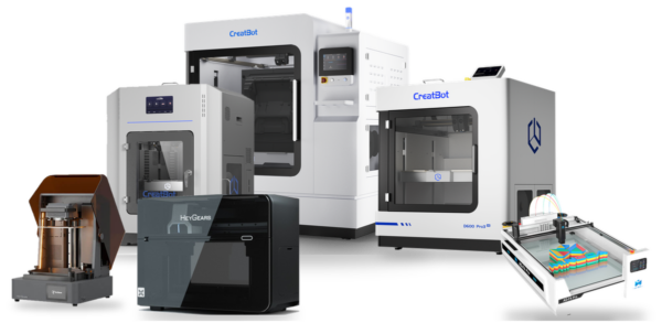
Printing helps around the tool rather than inside the cavity. Common uses in the industry include holding fixtures for machining and inspection, assembly and trim jigs, gauges, protective covers, and sample parts for early checks before steel is cut.
For heat-exposed fixtures, the CreatBot PEEK-250 lists a 480 C nozzle, a heated chamber up to 200 C and a 250 x 250 x 300 mm build volume, with PEEK and PEI named as target materials. For large holding tools, the CreatBot D800 Ultra lists an 800 x 650 x 650 mm build volume, a 420 C nozzle and carbon- and glass-fibre-filled grades. See our page on jigs, fixtures and end-use parts. We do not offer printed mould inserts or conformal cooling channels.
Video
Tell us the tool, its size and what you need to decide: wear, repair or modification. We will recommend a scanner or run it as a service.
We scan the tool and compare it with the original CAD or an earlier scan. The deviation map shows wear, flash risk and repair accuracy across the cavity. Repeat scans at set intervals to track wear over time. A demo on your own tool shows the result.
Yes. We scan the tool or component, then build a CAD model that matches its current state. You can use it to design a repair insert or a modification. Material and heat treatment stay with your tool room.
Often yes, with preparation. Polished or reflective steel may need a thin developer or spray for a clean scan. We test your tool before recommending a scanner, so you know the result in advance.
For large dies and tool bases, a tracked system such as the FreeScan Trak Nova suits a 2.6 x 2.2 m field of view. Smaller inserts are well served by the FreeScan Omni or Trio. Tell us the size and tolerance and we will confirm.
Yes. CreatBot industrial printers handle engineering filaments, and the PEEK-250 targets PEEK and PEI for heat-exposed fixtures. We can print a first fixture as a service so you can test it before buying a printer.
Yes. We scan tools and parts at our office or on your site and deliver a deviation report or a CAD model. WhatsApp us the tool details for a scoped quote.